Cadia Valley Operations Northern Tailings Storage Facility Embankment Slump

Disclaimer: This case study has been prepared solely by GDS Instruments following our review and interpretation of a publicly available technical report. This case study has not been reviewed by third parties, and does not constitute technical advice of any sort.

Read more below or download the case study here.

INTRODUCTION

During the afternoon of the 9th of March 2018, a mobile slump occurred in an approximately 300 m section of the southern embankment of the Cadia Valley Operations (Cadia) Northern Tailings Storage Facility (NTSF), located in central-west New South Wales, Australia. The embankment slump resulted in a release of tailings from the NTSF, with the released tailings captured within the adjacent South Tailings Storage Facility (STSF). Cracking (on the embankment crest) and thrusting (at the embankment toe) observed by Cadia site personnel earlier in the day enabled timely evacuation of the worksite, along with some downstream residential homes, prior to the slump occurring. This resulted in the slump creating no obvious social or environmental impacts.

An Independent Technical Review Board (the ITRB) was established to determine the technical causes of the Cadia NTSF embankment slump. The ITRB reported on its findings on the 17th of April 2019 (Jefferies et al., 2019), concluding that a previously unidentified low-density foundation layer in the vicinity of the slump had progressively deformed due to 
loading imposed by the embankment construction. When the rate of this deformation rapidly increased, tailings impounded within the NTSF liquefied, significantly increasing the load pushing on the embankment. The already-weakened foundation was ultimately unable to resist this increase in load, resulting in the embankment slumping.

This case study briefly summarises some of the geotechnical engineering findings reported by the ITRB. Specifically, it focuses on aspects of the advanced laboratory testing programme conducted during the investigation, for which, advanced monotonic and cyclic direct simple shear, triaxial, bender element, and constant rate of strain apparatuses designed and manufactured by GDS Instruments (GDS) were used. We strongly recommend that our readers refer to the publically available ITRB report, published by Newcrest Mining Limited (NML), for a full commentary on the Cadia NTSF embankment slump. A concise, ten-minute technical summary of the slump can also be viewed on the NML YouTube channel (Newcrest Mining Limited, 2019).


Figure 1: Aerial view of the Cadia NTSF southern embankment slump location as of the 13th of September 2018.

Source: Google Earth, Image © 2021 CNES / Airbus.
THE CADIA NORTHERN TAILINGS STORAGE FACILITY EMBANKMENT AND FOUNDATION

The NTSF was designed and constructed to impound tailings produced from gold and copper mining operations undertaken at Cadia. The initial NTSF embankment, completed in 1998, comprised an earth and rockfill starter dam of maximum 50 m height, with subsequent embankment raises intending to use modified centreline construction. By late 2016, the embankment had reached its initial target maximum height of 91 m, however a combination of downstream, centreline, and upstream construction was ultimately used to build the embankment raises.

In early 2017, an additional 3 m raise using upstream construction was begun (Stage 10), with the raise being completed in the vicinity of the slump location by mid-2017. 


Cone penetration tests (CPTs) performed in 2017 however led to concerns about embankment stability, resulting in the recommendation that two buttresses be constructed to improve stability under static and dynamic loadings (Stage 1 and Stage 2 buttresses, as shown on Figure 2). At the location of the slump:

  • The Stage 1 buttress began construction in late 2017, and was completed by the 5th of March 2018.
  • In January 2018, approximately 5.5 m of material was excavated from the embankment toe to prepare the foundation for Stage 2 buttress construction. The excavated material comprised over 4 m of accumulated tailings, along with some of the foundation material.
  • Construction of the Stage 2 buttress had not started at the time of the slump.

Figure 2: Simplified schematic section of the Cadia NTSF embankment during Stage 10. Note that Stage 2 buttress construction had not started at the time of the slump.

The generalised profile of the foundation materials in the vicinity of the slump is presented in Figure 3. While geological complexities at Cadia fall beyond the scope of this case study, it is important to note the presence of the Forest Reef Volcanics (FRV) Unit A layer close to the embankment foundation level, as this foundation material was determined to be the most significant feature contributing to the embankment slump. 
This was due to the FRV Unit A material being low density (void ratios of the order of 0.8 to 1.5), relatively weak, highly compressible, and displaying strain-weakening response when placed under load. It is important to note that the FRV Unit A had not been identified prior to the embankment slump occurring.


Figure 3: Simplified profile of foundation materials in the vicinity of the embankment slump. It is also noted that the embankment experienced two low-magnitude earthquakes (approximately MW 3, separated by ten seconds or so) on the day prior to the slump occurring (on the 8th of March 2018).

ITRB INVESTIGATION INTO THE CADIA NTSF EMBANKMENT SLUMP

The ITRB was tasked with determining the technical cause of the embankment slump. This led the ITRB to review the NTSF construction history, as well as to commission extensive subsurface field investigations, advanced laboratory testing, and advanced numerical analyses of the embankment under various loading conditions. Hydrogeological and seismological studies were also undertaken.

The laboratory testing programme commissioned by the ITRB enabled the loading response of the tailings, embankment, and foundation materials to be assessed, and provided material properties for use within the advanced numerical analyses. While many different tests were performed by numerous laboratories as part of the testing programme, this case study limits its focus to the advanced direct simple shear (DSS), triaxial, bender element, and constant rate of strain testing performed by Golder’s Perth laboratory (Golder; www.golder.com/testing-services/) on the tailings and FRV Unit A foundation materials. Please refer to Appendix D and Appendix E of the ITRB report for further details regarding the laboratory tests performed as part of the ITRB investigation.

ADVANCED LABORATORY TESTING OF TAILINGS & FRV UNIT A MATERIALS, INCLUDING USE OF GDS APPARATUSES

a) Monotonic and cyclic direct simple shear (DSS) testing.

Golder conducted 24 constant volume direct simple shear tests on a number of tailings gradations and FRV Unit A specimens as part of the advanced laboratory testing programme. This testing was undertaken using a GDS Electromechanical Dynamic Cyclic Simple Shear (EMDCSS) device, which enables a constant specimen volume to be maintained during shearing (monotonic and/or cyclic) via a low compliance DSS device design, active height control, and physical lateral restraint via a stack of low-friction retaining rings (alternatively, a wire-reinforced rubber membrane may also be used).

Figure 4: The GDS Electromechanical Dynamic Cyclic Simple Shear (EMDCSS) device.
Twelve reconstituted tailings specimens tested by Golder within the GDS EMDCSS device were nominally 100 mm diameter, and were consolidated to either 50 kPa or 300 kPa vertical effective stress. All test specimens were slightly looser than the estimated in-situ state of the tailings following consolidation.

Of the ten test specimens that were cyclically-sheared, eight had an initial shear stress bias applied during the consolidation stage (either 5 % or 30 % of the vertical effective consolidation stress). Sinusoidal cyclic loadings were applied 
to eight of the tesspecimens at a frequency of 1 Hz, while two specimens had custom cyclic loadings applied that simulated the ground motions of the two low-magnitude earthquakes experienced on the 8th of March 2018. Figure 5 displays the GDSLab software interface for users to define custom cyclic loadings when performing tests within a GDS EMDCSS.

Two test specimens were monotonically-sheared at a rate of approximately 5 % shear strain per hour.
Figure 5: GDSLab software interface for defining custom cyclic loadings when performing tests within a GDS EMDCSS.

Data gained from the constant volume cyclic DSS tests demonstrated that the two low-magnitude earthquakes that preceded the embankment slump (cyclic stress ratios of the order of 0.05) did not induce significant excess pore pressure build-up or shear strain within the tailings specimens. Specifically, excess pore pressures of the order of 10 % of the initial vertical effective stress were observed after five to fifteen load cycles had been applied, irrespective of static bias employed during consolidation.

Twelve FRV Unit A specimens tested by Golder within the GDS EMDCSS device were nominally 60 mm diameter, and were consolidated to between 250 kPa to 1200 kPa vertical effective stress. Test specimens were found to have post-consolidation dry densities in the range of 1.29 to 1.59 t/m3. An initial shear stress bias was not applied during the consolidation stages of these tests, and all were monotonically-sheared at a rate of approximately 2 % shear strain per hour. 
Nine of the test specimens were prepared from tube or block samples, while three specimen were remoulded using an in-house compaction procedure.

Data obtained from the constant volume monotonic DSS tests on specimens prepared from tube or block samples produced estimations of peak undrained strength ratios (i.e., peak shear stress divided by vertical effective consolidation stress) in the range of 0.26 to 0.56, depending on the consolidation stress and tube or block sampling location. Importantly, the specimens generally displayed strain-weakening behaviour (i.e., a reduction in shear stress) once the soil was strained beyond the peak shear stress, highlighting the brittle response of the FRV Unit A material. The post-peak average loss in strength was approximately 25 % (with a range of strength loss of approximately zero to 40 % loss).

Figure 6: Stress-strain response of a FRV Unit A specimen tested under constant volume monotonic 
DSS conditions within the GDS EMDCSS.


Figure 7: Photos of a clean sand specimen tested under constant volume conditions within a GDS Electromechanical 
Dynamic Cyclic Simple Shear (EMDCSS) device at the GDS office. This test was in no way related to the 
Cadia NTSF embankment slump investigation, and is shown for illustrative purposes only.

b) Triaxial testing

Golder performed 41 triaxial (TX) tests on a number of tailings gradations and FRV Unit A specimens as part of the advanced laboratory testing programme. This testing was undertaken using GDS Triaxial Automated Systems (GDS TAS), which employ an advanced velocity-controlled load frame and GDS pressure/volume controllers to apply axial and radial stresses to triaxial test specimens.


Figure 8: The GDS Triaxial Automated System (GDS TAS).

A total of 32 TX tests were performed by applying strain-controlled monotonic compression to isotropically consolidated tailings specimens under drained (20 tests) and undrained conditions (12 tests), with results used to determine critical state lines (CSL), as well as estimate strength parameters, for four different tailings gradations. Test specimens were reconstituted using in-house moist-tamping methods, and a minimum of 20 % axial strain was applied in each test, with an aim to reach critical state. A critical state effective friction angle equal to 34 ° was adopted for the tailings based on the TX test data obtained. 

An additional six TX tests were performed to observe the response of the tailings to a number of stress paths experienced during the construction of the latter embankment stages and the Stage 1 buttress. These tests, in which specimens were firstly anisotropically consolidated, and then loaded under drained or partially-undrained conditions, helped the ITRB to understand whether some points within the tailings may have approached an unstable stress state during embankment construction, such that a small amount of rapid loading could result in liquefaction of the tailings. 
To conduct the drained tests, termed ‘constant shear drained’ tests (CSD tests) by Golder, the triaxial system used must be able to apply and maintain a constant deviator stress to a test specimen, even when a specimen is rapidly collapsing (i.e., experiencing rapid axial straining). Golder used two triaxial configurations to achieve this criterion: One in which dead-weights were manually placed on a loading hanger, and another in which a GDS DigiRFM was installed within the GDS TAS. The DigiRFM introduces a rapid, direct feedback loop between the triaxial load cell and load frame, enabling the load frame to axially compress test specimens at over 90 mm per minute, maintaining the targeted deviator stress. Users interested in upgrading their GDSTAS to include a DigiRFM should contact GDS directly.

Figure 9: GDS DigiRFM installed within a GDS TAS.

Bender element (BE) testing was also performed on a single reconstituted TX tailings specimen. This enabled the shear wave velocity, and subsequently the small-strain shear modulus, to be estimated at various levels of applied effective confining stress, providing important inputs for the assessment of embankment response to earthquake shaking. BE tests were performed at 17 different mean effective confining stress values (ranging between approximately 20 kPa to 1090 kPa), with the testing conducted using a GDS Bender Element System (GDSBES).
Figure 10: GDS Bender Element System (GDSBES).


                      Figure 10: GDS Bender Element System (GDSBES).

Figure 11: Shear wave velocity and small-strain shear modulus estimates obtained from bender element testing of a single tailings TX specimen within a GDSTAS using a GDSBES. Specimen void ratio and bulk density estimates are also shown.


Three TX tests were performed by applying strain-controlled compression to isotropically consolidated undisturbed FRV Unit A specimens under undrained conditions. These tests again highlighted the strain weakening behaviour of the FRV  Unit A material, with peak and residual effective friction angles equal to 21.4 ° and 16.2 ° being estimated respectively (as well as effective cohesion values equal to 58.5 kPa and 0 kPa respectively).
Figure 12: Photos of an isotropicallly-consolidated fine-grained soil specimen tested under undrained monotonic strain-controlled compression conditions within a GDSTAS. This test was in no way related to the Cadia NTSF embankment slump investigation, and is shown for illustrative purposes only.

c) Constant rate of strain testing

c) Constant rate of strain testing

Golder conducted two constant rate of strain (CRS) tests on FRV Unit A specimens as part of the advanced laboratory testing programme. This testing was undertaken using a GDS Constant Rate of Strain (GDSCRS) system, in which an advanced velocity-controlled load frame is used to apply vertical stress to a laterally-confined, back-pressured test specimen. Back pressure is supplied via a GDS pressure/volume controller.


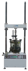
 Figure 13: The GDS Constant Rate of Strain system (GDSCRS).

The two CRS tests performed on FRV Unit A specimens enabled the ITRB to estimate values of typical consolidation parameters (e.g., coefficient of consolidation, pre-consolidation pressure), while also highlighting a reduction in the constrained modulus (i.e., one-dimensional stiffness) as the vertical effective stress increased beyond approximately 1000 – 1500 kPa. It was proposed that this reduction in stiffness at higher vertical stress levels was caused by soil particle crushing or disaggregation.


INSIGHTS FROM THE ADVANCED LABORATORY TESTING PROGRAMME

The advanced laboratory testing programme provided a number of important insights into the loading response of the tailings and FRV Unit A foundation materials, assisting the ITRB in understanding the mechanism by which the Cadia NTSF embankment slumped on the 9th of March 2018. These insights included:

  • Monotonic direct simple shear (DSS) testing of FRV Unit A specimens within a GDS EMDCSS highlighted the strain-weakening response of this previously unidentified embankment foundation material. This ultimately led the ITRB to conclude that the peak strength of this material had begun to be exceeded during embankment construction, particularly following excavation of material at the embankment toe and construction of the Stage 1 buttress, resulting in progressive deformation within the foundation. The deformation rapidly accelerated prior to the slump occurring.
  • ‘Constant shear drained’ (CSD) triaxial testing of reconstituted tailings specimens within a GDS TAS suggested that some locations within the tailings had approached an unstable stress state during embankment construction, and that rapid collapse could potentially being triggered (i.e., liquefaction could occur) should a small amount of rapid loading be applied. The accelerating deformation within the embankment foundation provided the trigger to cause the tailings to liquefy, which in turn significantly increased the load on the embankment and the already weakened foundation. This additional load could not be resisted, and the embankment slump occurred.
  • Cyclic DSS testing of tailings specimens within a GDS EMDCSS demonstrated that two low-magnitude earthquakes experienced at the Cadia worksite on the 8th of March 2018 did not induce significant excess pore water pressures and shear strains within the tailings. This finding was important, as it established that the low-magnitude earthquakes did not contribute to the embankment slump.
SUMMARY

A mobile slump that occurred in a section of embankment at the Cadia Valley Operations (Cadia) Northern Tailings Storage Facility on the 9th of March 2018 was determined to have been caused by progressive deformation of a previously unidentified low-density foundation layer during ongoing embankment construction, which ultimately triggered liquefaction of impounded tailings. Once liquefied, the tailings significantly increased the load applied to the embankment, which the already-weakened foundation was unable to resist. This resulted in the embankment slumping, however timely evacuation of the worksite by Cadia personnel meant the slump created no obvious social or environmental impacts.

The technical cause of the embankment slump described above was concluded through investigation by an Independent Technical Review Board (ITRB). A laboratory testing programme was commissioned as part of the ITRB investigation, with a number of advanced test apparatuses produced by GDS Instruments (GDS) being utilised by Golder’s Perth laboratory (Golder) to produce monotonic and cyclic direct simple shear (DSS), triaxial, bender element, and constant rate of strain test data. Such testing provided the ITRB with important insights into the response of the tailings and foundation materials to load, assisting the ITRB in determining the technical mechanism of the slump. The testing also helped the ITRB to rule out two lowmagnitude earthquakes as the cause of the tailings liquefying. This case study therefore demonstrates the value advanced laboratory testing programmes can provide when assessing how foundation soils and impounded materials may perform under loadings applied by embankment construction, and/or seismic activity, at tailings storage facilities. 


REFERENCES 

Jefferies, M.; Morgenstern, N. R.; Van Zyl, D.; Wates, J. (2019). Report on NTSF Embankment Failure Cadia Valley Operations for Ashurst Australia By Independent Technical Review Board. 17 April 2019. Newcrest Mining Limited. https://www.newcrest. com/sites/default/files/2019-10/190417_Report%20on%20 NTSF%20Embankment%20Failure%20at%20Cadia%20for%20 Ashurst.pdf. 

Newcrest Mining Limited. (2019). Cadia NTSF Embankment Slump. Available at: https://www.youtube.com/ watch?v=DyyxLmPdVaE.