GDS Bender Elements System

The GDS Instruments Bender Element System enables easy measurement of the maximum shear modulus of a soil in a triaxial cell. Measurement of soil stiffness at very small strains in the laboratory can be difficult due to insufficient resolution and accuracy of load and displacement measuring devices. The capability exists to regularly carry out measurements of small strain stiffness in the triaxial apparatus using local strain transducers, but this can be expensive and is generally confined to research projects. The addition of a set of Bender Elements to a triaxial testing system makes the routine measurement of Gmax (maximum shear modulus), simple and cost effective.

Read below or Click here to download the case study.


THE PROBLEM

When performing bender element tests, good contact or ‘coupling’ with the soil is critical to obtaining clear results. On a soil sample, the element can either be pushed in, as in the case for soft clay, or created around the element itself for samples such as sand.

Performing bender element tests on rocks however can create a problem, because it is not obvious how to insert the element. At GDS we decided to investigate this problem.


THE SOLUTION


Using a sample of sandstone as our test piece, we decided to carefully carve a slot in each end suitable for the bender element to be inserted. This was performed with a craft knife. The slots were deep enough such that the elements could be cleanly inserted into the ends of the sandstone unobstructed (great care was taken to ensure the slots were not too big, in fact they were ‘just’ large enough to house the bender element), see Fig 1.

The slots were then filled with soft clay to provide the coupling between the bender element and the sandstone. 


Once we were happy that there was a good fit between the element and the sample we rolled up the membrane, inserted the sample in to a triaxial cell and ran a series of tests, to determine the accuracy of this sample preparation method.

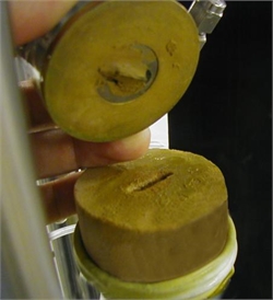
Fig 1. Shows the sandstone sample with the slot cut out for the bender element.

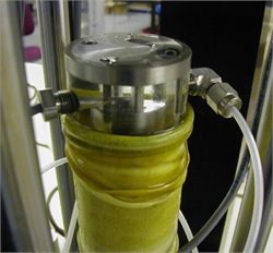
Fig. 2 Shows the bender element sample within the triaxial cell.


RESULTS


The results for our test were recorded using the GDS dedicated Bender Elements software. To cater for the many different approaches to bender element testing, the GDS Bender Element software allows the following waveforms to be used when running a test.

  • Sine wave,
  • Square wave,
  • User defined.

We used a sine wave for our series of tests.


Bender element tests were performed on the sample isotropically loaded to cell pressures of 300kPa, 600kPa and 900kPa. Back pressure was zero in each test. As can be seen in the 3 graphs showing source against receiver, the results were very clear. Shear wave velocities obtained by comparing peak source with peak received trace showed the following:-


Isotropic Stress - Shear Wave Velocity
300kPa - 660.7m/s
600kPa - 698.1m/s
900kPa - 725.5m/s

Fig 3. Graph showing results from the S-wave 300kPa test.

Fig 4. Graph showing results from the S-wave 600kPa test.

Fig 5. Graph showing results from the S-wave 900kPa test.


CONCLUSION

The clarity of the received trace was considered to be the same as when performed on soil samples. The method was therefore considered a success. One of the reasons it has been possible to use the GDS bender element to perform this test is down to the length of the GDS element. The length that the bender element protrudes into the sample has been optimised without compromising the power transmitted from or received to the element. This is achieved by fixing the element further down inside the insert and then filling the remaining volume with flexible material. This allows the element to achieve maximum flexure at its tip, whilst only protruding into the sample by a reasonable distance (only a few mm). Advantages of this include prolonged life of the elements by increased resilience to breakage and easier sample preparation, particularly on very stiff samples where only a small recess for the element is required.


Fig 6. The Bender Elements System (GDSBES) from GDS Instruments

Customer Testimonial from GDSBES User:

"I must say that I have had an excellent experience with GDS. All of your staff have been extremely helpful and responsive to all of my requests. When I originally purchased the Bender Elements, the GDS staff did an excellent job in providing shop


drawings and manuals to be used in modifying my existing triaxial system. I will certainly be using GDS again in the future. Thank you for your past assistance."

Useful link: http://www.gdsinstruments.com/datasheets/BENDER_ELEMENTS_Datasheet.pdf

Products Features in Case Study